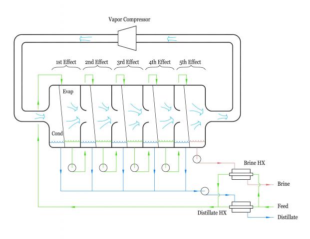
The simplified flow diagram shows how multiple effect vapor compression distillation works. Feed enters the plant and is split into two streams. One stream enters the brine heat exchanger (Brine HX) where it is heated by cooling the hot brine leaving the plant. The other stream enters the distillate heat exchanger (Distillate HX) where it is heated by cooling the hot distillate leaving the plant. The pre-heated feed streams are then joined back into one stream and enter the first effect of the evaporator. Here, part of the feed is evaporated and the balance is pumped from the first effect and enters the second effect. Here again, part of the feed is evaporated and balance is pumped from the second effect and enters the third effect. This process is repeated until the fifth effect where the brine is taken out, cooled in the brine heat exchanger, and discharged from the plant. The vapor generated in the first effect flows in to the second effect and condenses on the cooler heat transfer surface there and is taken out as distillate. The heat released in condensing the vapor in the second effect is transferred across the heat transfer surface (slanted line) and causes the evaporation of the equivalent amount of water from the feed in the second effect. This process is repeated in the third, fourth, and fifth effects to produce distillate streams from each effect. The vapor generated in the fifth effect is taken out, compressed to raise its saturation pressure and temperature, and is then introduced to the condensing side of the first effect where it condenses on the heat transfer surface and is withdrawn as distillate. The condensate streams from each of the five effects are combined, then cooled in the distillate cooler and taken out of the plant.
Key points about vapor compression distillation systems:
- Production capacity is proportional to the total heat transfer surface area (plant size). The more heat transfer area in a plant, the more distillate it produces.
- For each effect included in a multiple effect vapor compression distiller, the compressor size is reduced proportionally. That is, the compressor of a five-effect system is 1/5 the size of a single-effect system – assuming the total heat transfer area (and thus the distillate production capacity) is the same in either case.
- There is a gain in energy efficiency by using multiple effects instead of a single effect due to the step-wise concentration of the feed solution.
- Because only the last effect in a multiple-effect system is subjected to highly concentrated liquid, service needs are accordingly reduced.
- Using evaporators, such as the WFRD, that have high overall heat transfer coefficients causes a reduction in both plant size (heat transfer surface area), and specific energy consumption.
- Using evaporators, such as the WFRD, that have high overall heat transfer coefficients causes a reduction in CapEx, and a reduction in OpEx.
Copyright © All rights reserved. WRT 2017
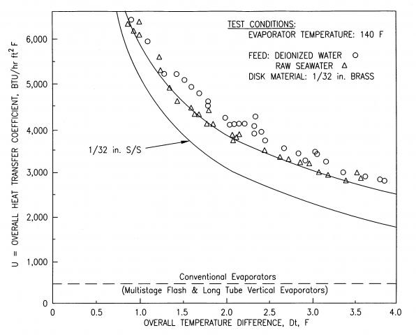
Overall heat transfer coefficient of the WFRD evaporator